
Railway operations present 5 types of danger: derailment, head-on collision, rear-end collision, side swipe and collision with an obstacle. Because humans can make mistakes, operators have introduced systems to limit some of these risks: these are Automatic Train Protection (ATP) systems.
These systems are installed on the track and on board the trains. They automatically apply the brakes when train movement exceeds the limits authorised by the signalling system, thereby reducing the risks.
Over time and in Europe, ATPs become obsolete, as they complicate border crossings, because each country has its own system. This is why a European ATP has been designed: ERTMS/ETCS, and it will be essential in the coming years.
Latest update: 2026-01
Automatic Train Protection by Bastian Simoni is licensed under CC BY-NC-SA 4.0![]()
![]()
![]()
![]()
1. Introduction
1.1 Railway hazards
According to French railway safety agency EPSF [1], following dangers exist in railway operations:
- Derailment: an incident or accident in which a railway vehicle leaves the rails, either fully or partially, with various possible causes (equipment or infrastructure failure, excessive speed, etc.);
- Head-on collision: a frontal collision between two trains;
- Rear-end collision: a collision from behind when a train hits another train in front of it;
- Side swipe: a lateral collision between two trains that occurs at an intersection or junction of tracks;
- Collision with an obstacle (rockfall on the track, a road vehicle present at a level crossing, etc.).
To mitigate some of these hazards, railway operators have implemented solutions. For example, signals along the tracks that the driver must adhere to. However, this is not always sufficient.
In GoA0, i.e., in manual operation, the driver’s vigilance is not always assured. This is why automation systems have been developed to supervise the movement of the train : this marks the beginning of GoA1.
1.2. The introduction of automated systems
Operators have introduced devices, such as the crocodile in France, invented in 1872. [2] The crocodile is a device installed at the foot of each signal. It alerts the driver with an audible beep in the cab when a restrictive signal is passed. The driver then has a few seconds to acknowledge the information by pressing a button. If the information is not acknowledged within the allotted time, the train stops automatically.
The German PZB system, the first version of which was developed in the 1930s, equipped 32,398 km of the federal network in 2019. [3] This device has three functions: to apply the brakes when passing closed signals, to monitor that a maximum speed is not exceeded on a section of track, and to monitor the driver’s acknowledgement that warning signals have been passed. The PZB is an ATP (Automatic Train Protection) system.
In France, the crocodile is not enough to prevent rail accidents. In the 1980s, SNCF decided to equip its trains with an ATP: the KVB (Contrôle de Vitesse par Balises). The KVB is a compulsory piece of equipment on a train before it can run on the French network.
2. Automatic Train Protection principles
2.1 Functionality
The function of an ATP is to protect the movement of a train, thereby helping to limit the dangers inherent in the railway system.
To do this, an ATP retrieves signalling information at all times, based on the systems installed on the track:
- The interlocking, which transmits to the ATP the status of all the signals for which it is responsible,
- The signals themselves, when a connection to the interlocking is not possible or not relevant.
Trackside signalling systems are completely agnostic about the trains running on the infrastructure. To supervise train movements correctly, the ATP relies on on-board information:
- Train properties, entered into the ATP by the driver: length, mass.
- Speed and position of the train in a positioning referential,
The ATP combines all this information to check whether train movement is authorised:
- The train is travelling at a speed that does not exceed a speed limit,
- The train is travelling within an envelope authorised by the trackside signalling, and therefore by the ATP.
If this is not the case, the ATP automatically applies the brakes, thanks to a direct connection with the train.
For high-speed traffic, where it is no longer possible to observe signals along the track, the cab signalling function has been developed for certain ATPs, such as the Transmission Voie-Machine (TVM) in France, or the Linienzugbeeinflussung (LZB) in Germany. As a result, it is now possible to dispense with side signalling altogether, and operate solely on the basis of an ATP offering cab signalling.

2.2 Architecture
To operate, the ATP must be located both on the trackside and on board. The ATP is therefore divided into two sub-systems:
- Trackside: to retrieve signalling information wherever required and send it to the onboard unit,
- Onboard:
- to retrieve signalling information from the trackside subsystem,
- to retrieve from the driver the properties of the train whose movement is to be supervised (length, mass),
- to retrieve the train’s speed and estimate its position,
- to provide cab signalling to the driver, when the ATP offers this function,
- to stop the train when movement is not authorised.
A track to train interface appears between the two subsystems (also known as an airgap). This interface is an integral part of the ATP system.

2.3 Constituents
Let’s now take a closer look at the constituents of the on-board and trackside subsystems.
The trackside ATP (ATP-TS), whose function is to retrieve signalling information and transmit it to the on-board system, is made up of the following elements:
- Encoder, a device which interfaces with the trackside signalling system (signals, interlockings), and which adapts this information, in the ATP’s own language,
- Transmitter, which transmits the information adapted by the encoder to the train.
The on-board ATP (ATP-OB), which supervises train movements and displays signalling in the cab (for ATPs offering this option), is made up of the following constituents:
- Antenna, which recovers the data transmitted by the trackside transmitter,
- Odometer, a device for estimating the distance travelled by the train and its speed,
- Train interface, which controls inputs/outputs to the train, in order to apply emergency braking, for example,
- Driver-machine interface, a device in the driver’s cab, enabling the driver to interact with the ATP (train property information; cab signalling),
- Computer, the on-board computer, which, on the basis of the information received from the antenna, the odometer and the train data entered by the driver, automatically applies the brakes via the train interface if the movement is not compliant, and displays the signalling on the driver-machine interface.

Below are a few examples of on-board computers: KVB (France) and PZB (Germany).
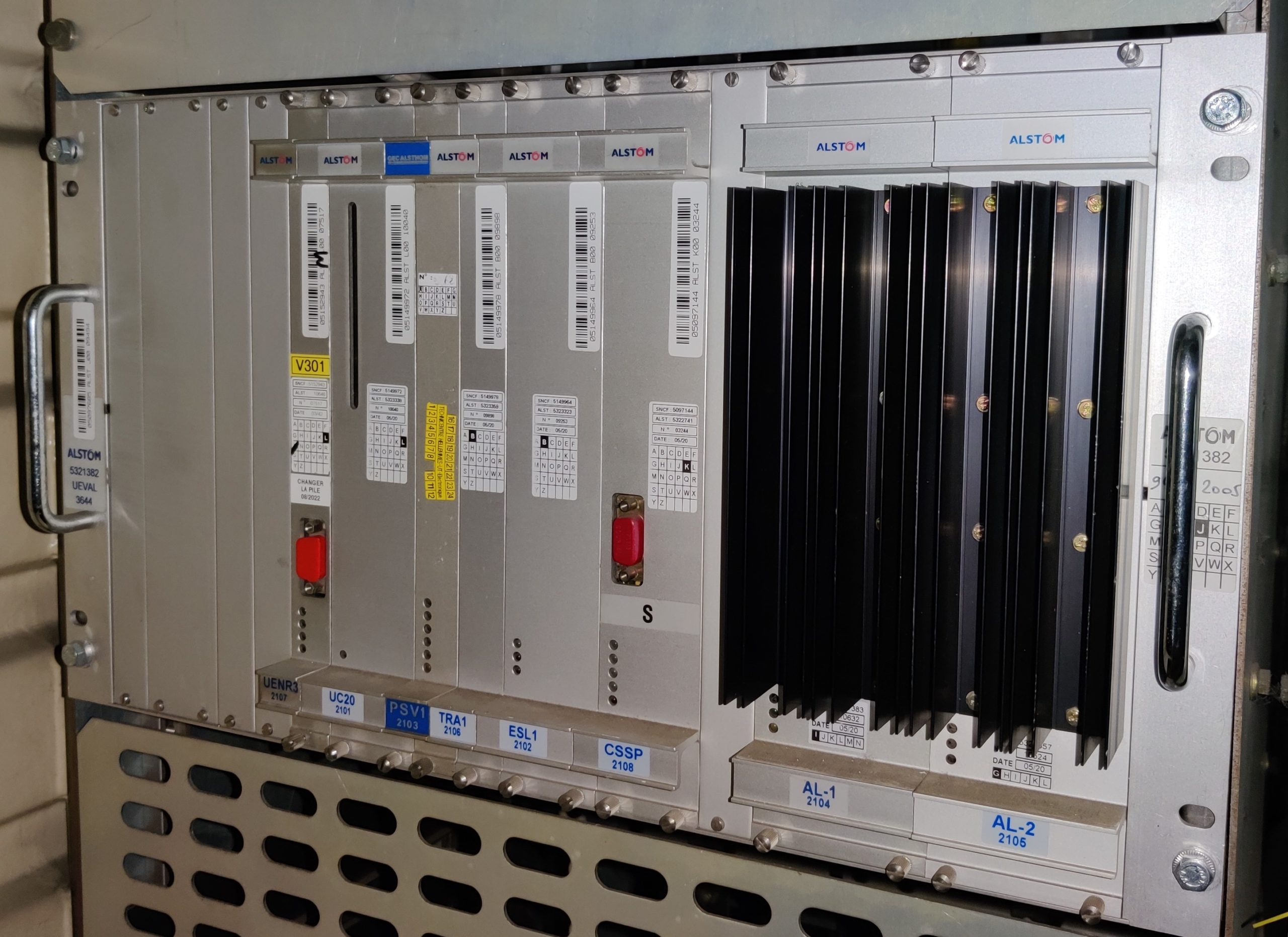
Calculateur UEVAL KVB Legacy (credit Bastian SIMONI)
Calculateur UEVAL KVB Legacy
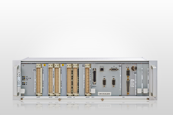
Onboard computer ATP PZB I60R (credit Bietergemeinschaft I60R)
Onboard computer ATP PZB I60R (credit Bietergemeinschaft I60R)
2.4 National systems and the interoperability issue
France equipped itself with its own protection system, the KVB, in the 1980s. Other countries in the European Union have called on their national industries to equip themselves with systems for protecting trains. Some systems also display signalling information in the cab.
The construction of high-speed lines has created a problem: drivers can no longer see the signals along the tracks at high speeds. A system displaying signalling information in the cab is therefore necessary. As a result, operators have called on their national manufacturers to design these systems. This has led to a wide variety of protection systems within the EU.
These systems all have a specific airgap interface, which means that the systems are incompatible with each other. As a result, a train operating in different EU countries must equip itself with all the ATPs required by each network. This is a major obstacle to interoperability.
Interoperability means the ability of a rail system to allow the safe and uninterrupted movement of trains which accomplish the required levels of performance.
")
Red Eurostar capable of operating in 4 countries and equipped with 7 on-board signalling systems. Credit: Eurostar.
The red Eurostar, the high-speed train between Paris-Cologne-Amsterdam, is an emblematic example of the difficulty posed by multiple protection systems in Europe. In order to run in France, Belgium, the Netherlands and Germany, this train is multi-system, i.e. equipped with several different on-board ATPs [4]:
France: Crocodile (Cro), KVB, TVM
Germany: PZB, LZB
Belgium: TBL
Netherlands: ATB

All these ATPs need space inside the train (computer cabinets, sensors and under-frame antennae). Integrating them is a highly complex and costly task. Furthermore, the driver has to be trained to use all these systems, making his job more difficult. Finally, maintaining a train with all these systems over time represents cost.

2.5 Towards a harmonised system in Europe: ERTMS
With the existence of more than 20 different protection systems in Europe becoming a major obstacle to interoperability, the development of a standardised ATP began to be discussed at the end of the 1980s. The European Commission took up the issue in 1995, defining a strategy for the development of this system. Several signalling companies, grouped together in a structure called UNISIG, drew up the specifications for the system in 1998. [5]
The specifications gave rise to the first standard ATP: ETCS (European Train Control System). Today, national ATPs are obsolete. They are referred to as legacy systems or Class B systems in the European Union’s nomenclature. Class B systems must be replaced by ETCS.
With the creation of ETCS, a harmonised technical system was born: ERTMS.
Next article: ERTMS, the european rail traffic management system
Crédit photo de couverture : Bastian Simoni.
Références :
[1] https://securite-ferroviaire.fr/la-securite-ferroviaire/comprendre-la-securite-ferroviaire
[2] https://fr.wikipedia.org/wiki/Crocodile_(signalisation_ferroviaire)
[3] https://fr.wikipedia.org/wiki/Punktf%C3%B6rmige_Zugbeeinflussung
[4] https://www.ertms.net/wp-content/uploads/2021/06/9.-A-unique-signaling-system-for-Europe.pdf
[5] https://www.ertms.net/wp-content/uploads/2021/06/8.-ERTMS-History.pdf