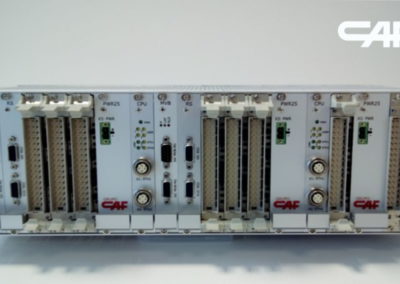
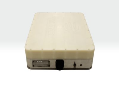
ERTMS/ETCS is the European Train Control System. As a safety system, ERTMS/ETCS supervises train movement based on signaling information, track data, speed, and train properties. It is a fundamental system for making the European railway area more integrated and attractive.
Let’s explore the principles of manual driving supervised by a protection system, the motivations behind the creation of ERTMS/ETCS, its components, blind spots, and possible developments.
ERTMS/ETCS is a technical system that is an integral part of the harmonized ERTMS system. If you haven’t already, I recommend reading the article ERTMS: the European rail traffic management system first.
ERTMS : the european rail traffic management system
Summary
In order to improve the safety of railway operations, many countries in Europe have adopted Automatic Train Protection (ATP) systems. Following the principle of “Ten engineers, ten solutions,” ATP systems in Europe all have their own specificities. This has made cross-border railway operations even more challenging, as trains must be equipped with all the ATP systems required by the different countries they pass through.
To address this situation and contribute to interoperability, a European Automatic Train Protection system was designed: ERTMS/ETCS.
Consisting of trackside equipment and onboard trains, ERTMS/ETCS has the main functions of providing signaling information in the cabin and supervising driving.
Different levels of application are proposed: 0, 1, 2, and NTC. They allow for a progressive migration between train equipment and track equipment. The different operating modes of the onboard equipment indicate the responsibilities between the ERTMS/ETCS system and the driver.
Twenty years after being specified by operators and manufacturers, the ERTMS/ETCS system is still deployed to a limited extent, both on the ground and onboard trains. One reason is the lack of strong political will for a significant deployment of ERTMS/ETCS. Another reason lies in the difficulties of integrating ERTMS/ETCS into the existing railway system.
Solutions to these integration challenges are starting to emerge. The goal is to scale up and move towards a massive deployment of the ERTMS/ETCS system in the Union. To achieve this, it will be necessary to move towards a logic of harmonized, mass-deployable products. This is the mandate of the Europe’s Rail initiative, which continues the work of harmonization, both operationally and technically, to address all the still-specific parts of ERTMS/ETCS.
On the technological front, ERTMS/ETCS continues to evolve. Specifications for level 2 without trackside train detection, hybrid level 3, and absolute positioning are underway in R2DATO.
The introduction of compatibility with Automatic Train Operation (ATO) and with the FRMCS ground-to-train communication were the major innovations of ERTMS/ETCS in 2023.
Last revision : 29/07/2024.
ERTMS/ETCS : the european train control system by Bastian Simoni is licensed under CC BY-NC-SA 4.0
1. Introduction
1.1 Railway Grades of Automation
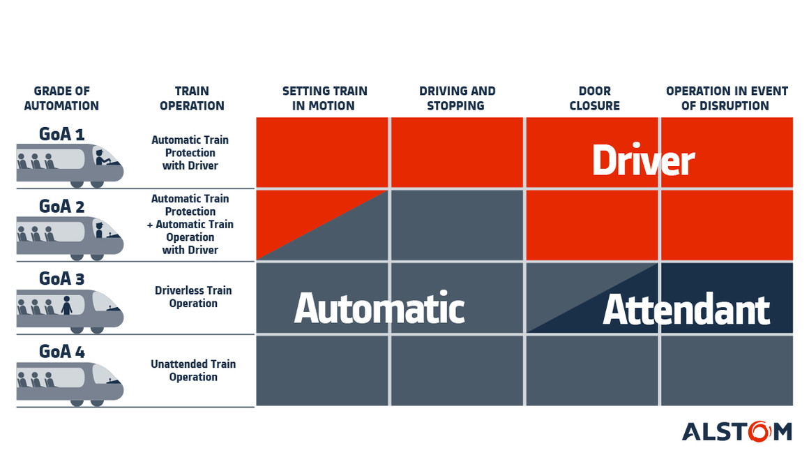
Rail signaling and automation technologies offer different levels of train operation automation. A definition proposed by the UITP (International Association of Public Transport) is the Grade of Automation (GoA), ranging from 0 to 4.
- GoA0: Manual operation,
- In manual operation, the driver accelerates and brakes the train based on what they see in the environment (signals, obstacles, hazards). No device is there to supervise their driving. Manual operation is commonly used for tramways, where speeds remain low.
- GoA1: Supervised operation by a protection system,
- GoA1 provides a first level of automation, as the operation is supervised by an Automatic Train Protection (ATP) system.
- An ATP can protect the train against passing closed signals or exceeding a speed limit by automatically applying emergency braking.
- GoA2: Automated traction and braking,
- In this level, an autopilot generates traction and braking commands and sends them to the train instead of the driver: this is the Automatic Train Operation (ATO).
- The ATO generates these commands based on the signaling limits provided by the ATP, while respecting the mission schedules to be carried out. The ATP continues its supervision and automatically applies emergency braking if the ATO does not comply with the signaling.
- The driver remains in the cab and continues to observe the environment to take over in case of degraded situations.
- GoA3: Autonomous train, with onboard personnel,
- In GoA3, there is no longer a driver in the cab. Environmental hazards (obstacles, dangers) must be supervised by other means.
- Personnel remains on board to advise passengers and intervene in case of contingencies.
- GoA4: Autonomous train, without onboard personnel,
- This is the most advanced level of automation, in which there is no onboard personnel.
- This is the degree of automation of driverless metro systems.
1.2 GoA1 : supervised driving
1.2.1 The need : to protect the trains
According to French railway safety agency EPSF, following dangers exist in railway operations:
- Derailment: an incident or accident in which a railway vehicle leaves the rails, either fully or partially, with various possible causes (equipment or infrastructure failure, excessive speed, etc.);
- Head-on collision: a frontal collision between two trains;
- Rear-end collision: a collision from behind when a train hits another train in front of it;
- Side swipe: a lateral collision between two trains that occurs at an intersection or junction of tracks;
- Collision with an obstacle (rockfall on the track, a road vehicle present at a level crossing, etc.).
To mitigate some of these hazards, railway operators have implemented solutions. For example, signals along the tracks that the driver must adhere to. However, this is not always sufficient.
In GoA0, i.e., in manual operation, the driver’s vigilance is not always assured. This is why automation systems have been developed to supervise the movement of the train : this marks the beginning of GoA1.
1.2.2 The introduction of automated systems
Operators have implemented first protection systems, such as the “crocodile” in France, invented in 1872.
The crocodile is a device installed at the foot of each signal. It alerts the driver with an audible alarm in the cabin when passing a signal displaying a restrictive aspect. The driver then has a few seconds to acknowledge the information by pressing a button. In the absence of acknowledgment within the specified time, the train automatically stops.
The German PZB system, whose first version was developed in the 1930s, equipped 32,398 km of the federal network in 2019.
This device has three functions: applying braking when crossing closed signals, monitoring non-exceedance of a maximum speed on a section of track, and monitoring the driver’s acknowledgment of crossing warning signals. The PZB is part of train protection systems: the ATPs.
In France, the crocodile is not sufficient to prevent railway accidents. During the 1980s, SNCF decided to equip its trains with an ATP: the KVB. The Contrôle de Vitesse par Balises (KVB) is a mandatory equipment on a train, allowing it to operate on the French network.
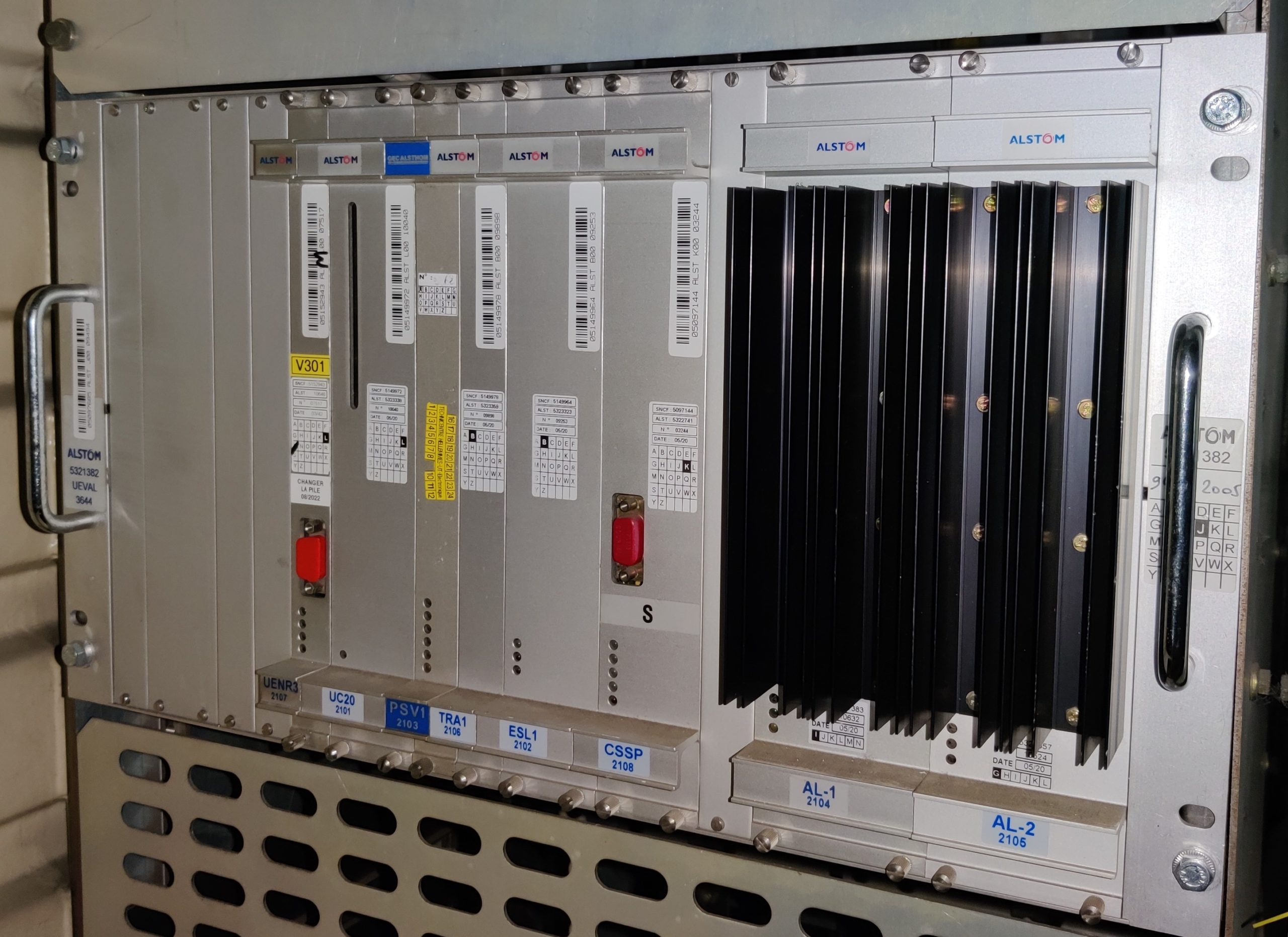
Onboard computing unit UEVAL (Unité d’EVALuation) of French ATP KVB.
Credit : Bastian SIMONI
1.3 ATP Principles
1.3.1 Generic principles
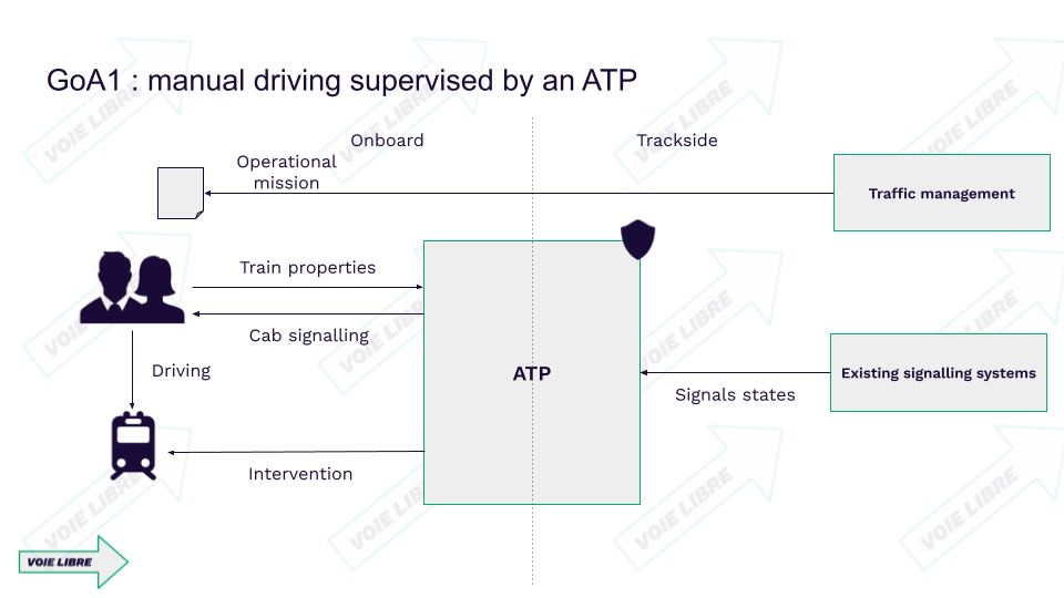
In general, an ATP functions to ensure the movement protection of a train, thereby helping to mitigate the inherent hazards of the railway system. To achieve this, an ATP continuously retrieves signaling information based on trackside systems:
- Interlocking, which transmits to the ATP the states of all signals under its responsibility.
- The signals themselves, when a connection to the interlocking is not possible or not relevant.
Trackside signaling systems are entirely agnostic to the trains operating on the infrastructure. Therefore, to properly supervise train movement, the ATP relies on onboard information:
- Train properties, inputted into the ATP by the driver,
- Train speed and position in a positioning reference system (often a reference system specific to the ATP).
The ATP combines all this information to verify if the train movement is authorized:
- The train is traveling at a speed that does not exceed a speed limit.
- The train is within an envelope allowed by the ground-based signaling, thus by the ATP.
If this is not the case, then the ATP automatically applies braking, thanks to a direct connection with the train.
For high-speed operations where observing signals along the track is no longer feasible, the cab signaling function has been developed for certain ATPs such as Transmission Voie-Machine (TVM) in France or Linienzugbeeinflussung (LZB) in Germany. Consequently, it is possible to entirely rely on cab signaling and remove lineside signaling.
1.3.2 ATP decomposition
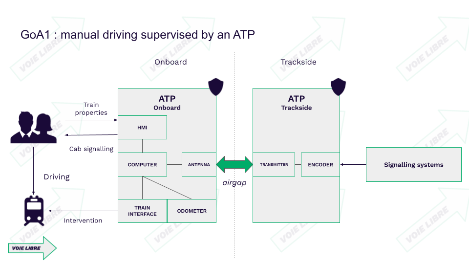
The operation of the ATP requires it to be both on the trackside and onboard. Therefore, the ATP is divided into two subsystems:
- Trackside:
- to retrieve signaling information wherever required and transmit it to the onboard system,
- Onboard:
- to receive signaling information from the trackside subsystem,
- to receive train properties from the driver that need to be supervised (length, mass),
- to retrieve the train’s speed and estimate its position,
- to provide cab signaling to the driver when the ATP offers this function,
- to intervene on the train when movement is not authorized.
An interface between the trackside and onboard systems appears between the two subsystems (also called an airgap). This interface is an integral part of the ATP system.

1.3.3 ATP constituants
Now let’s take a closer look at the components of the onboard and trackside subsystems.
The trackside ATP, which retrieves signaling information and transmits it to the onboard system, consists of the following elements:
- Encoder: a device that interfaces with the trackside signaling system (via sensors, digital interfaces, etc.) and adapts this information into the ATP’s language,
- Transmitter: which sends the information adapted by the encoder to the train.
The onboard ATP, which supervises train movements and displays signaling in the cabin (for ATPs offering this option), consists of the following elements:
- Antenna: which retrieves data transmitted by the trackside transmitter,
- Odometer: a device for estimating the distance traveled by the train and its speed,
- Train interface: which controls inputs/outputs to the train to apply emergency braking, for example,
- Human-Machine Interface (HMI): a device in the driver’s cabin allowing interaction with the ATP (entering train properties, cabin signaling),
- Computer: which, based on information received from the antenna, odometer, and train data entered by the driver, automatically applies emergency braking via the train interface if the movement is not compliant and displays signaling on the HMI.
1.4 National ATPs and the interoperability issue
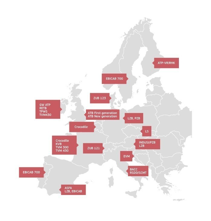
France equipped itself with its protection system, the KVB, in the 1980s. Other countries in the European Union turned to their national industries to equip themselves with systems for train protection. Some systems also allow for the display of signaling information in the cabin.
Indeed, the construction of high-speed lines has brought about a challenge: the driver can no longer perceive signals along the tracks at high speeds. A system displaying signaling information in the cabin is therefore necessary. Consequently, operators turned to their national manufacturers to design these systems. This has led to a wide variety of signaling systems within the Union, making interoperability difficult and costly.
‘interoperability’ means the ability of a rail system to allow the safe and uninterrupted movement of trains which accomplish the required levels of performance.
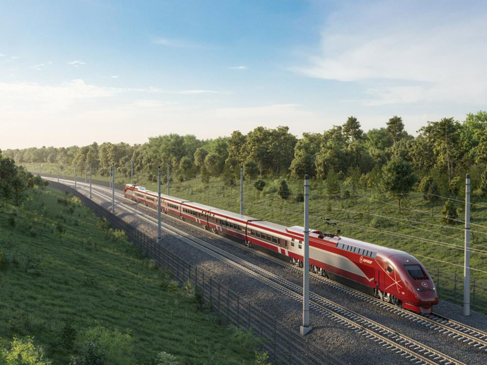
The red Eurostar, the high-speed train between Paris-Cologne-Amsterdam, is an emblematic example of the challenge posed by the multiple protection systems in Europe. In order to operate in France, Belgium, the Netherlands, and Germany, this train is equipped with 7 different onboard ATPs
- France: crocodile, KVB, TVM
- Germany: PZB, LZB
- Belgium: TBL
- Netherlands: ATB
Credit : Eurostar
1.5 An heterogenous european railway system
All these protection systems consume space inside the train (computer cabinets, sensors, and undercarriage antennas). Their integration is a very complex and costly task. Additionally, the driver must be trained in the use of all these systems, making their job more complex. Finally, maintaining a train with all these systems over time represents a significant cost.
These various complex protection systems greatly complicate the interoperability of the European railway system. Consequently, the idea of replacing these systems with a single protection and cabin signaling system in Europe emerged in the late 1980s.
1.6 Towards the genesis of a harmonized technical system in Europe: ERTMS
It was with the EC Directive 1996 on the interoperability of the high-speed railway network that the concept of an interoperable signaling control system, as well as the characteristics of ERTMS, were introduced.
Signaling industry manufacturers, grouped under a structure called UNISIG, produced the first technical specifications of ERTMS in 2000.
In 2002, the European Commission introduced ERTMS specifications into the Technical Specification for Interoperability – Control-Command and Signaling for the trans-European high-speed railway network (Commission Decision 2002/731/EC). Since then, the installation of ERTMS has become mandatory on new high-speed lines falling under the trans-European network.
In 2006, the first Technical Specifications for Interoperability concerning the trans-European conventional railway network were published by the Commission (Commission Decision 2006/679/EC).
Finally, in 2012, the Technical Specifications for Interoperability of Control-Command Signaling were merged to cover both the high-speed and conventional networks (Commission Decision 2012/88/EU).
To date, national ATPs are obsolete. They are referred to as legacy systems or class B systems in the European Union nomenclature. Class B systems must be replaced by the ERTMS/ETCS ATP.
2. ERTMS/ETCS Principles
2.1 Introduction
The starting point is the Movement Authority (MA). It is the permission for a train to operate its journey at a given maximum speed up to a certain point (this point being the end of the movement authority).
In the early days of railways, the movement authority was a hand signal given by a trackside agent, and then by mechanical and light signals installed along the tracks. With the construction of high-speed lines, where it is no longer possible to observe lateral signals, cabin signaling was invented. National ATP systems dedicated to high speed, such as TVM (France) or LZB (Germany), directly display the movement authority to the driver in the cabin.
ERTMS/ETCS follows exactly the same principles as a standard ATP, as we have seen before. It aims to transmit the movement authority from the trackside to the train, so that:
- the information is displayed to the driver on the cabin screen: this is cabin signaling,
- the onboard system supervises the train’s movement according to this movement authority and the train’s properties.
To perform its functions, ERTMS/ETCS consists of several subsystems, some on the trackside and others on board the train. The key element of ERTMS/ETCS lies in the standardization of the air gap, the interface between trackside and onboard systems.
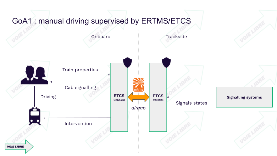
This standardization of the track-to-train interface enables interoperability, regardless of the supplier used. Thus, a train equipped with an ERTMS/ETCS onboard system from CAF can perfectly communicate with an ERTMS/ETCS trackside system from Hitachi.
2.2 Onboard subsystem
The onboard contains all elements necessary to :
- display the Movement Authority to the driver,
- apply the emergency braking in case of overspeed,
- apply the emergency braking in case of overshoot of the End of Authority,
- train positioning on the track plan.
The onboard subsystems rely on a safety computer: the European Vital Computer (EVC), and peripherals:
- the display in the cabin: Driver Machine Interface (DMI),
- antennas to fetch the signalling information from the trackside,
- the odometer, to determine the position of the train on the track plan.
The basic parameter for ETCS on-board functionality describes all the functions needed to run a train in a safe way. The primary function is to provide automatic train protection and cab signalling:
(1) setting the train characteristics (e.g. maximum train speed, braking performance);
(2) selecting the supervision mode on the basis of information from trackside;
(3) performing odometry functions;
(4) locating the train in a coordinate system based on Eurobalise locations;
(5) calculating the dynamic speed profile for its mission on the basis of train characteristics and of information from trackside;
(6) supervising the dynamic speed profile during the mission;
(7) providing the intervention function.
2.3 Trackside subsystem
The trackside subsystem is composed of all elements necessary to elaborate the Movement Authority, and to transmit it to the onboard.
The fundamental elements are the following:
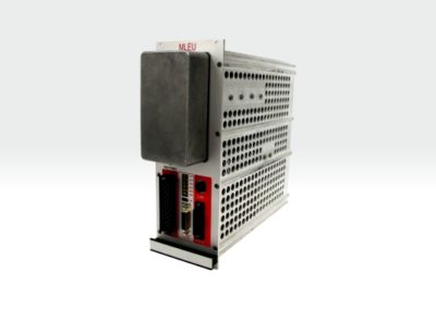
- Lineside Electronic Units (LEU), coders that retrieve the signalling information from the lineside signal or the interlocking, convert it into ERTMS/ETCS compliant information, and transmit it to Eurobalises,
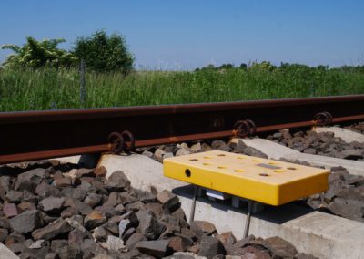
- Eurobalises, that transmit the ERTMS/ETCS compliant information (fixed or switchable via LEU) at the passing of the train,
- Radio Block Centre (RBC), that retrieves the signalling information from the interlocking, converts it into ERTMS/ETCS compliant information, and transmits via radio to the onboard units.
This Basic parameter describes the ETCS trackside functionality. It contains all ETCS functionality to provide a safe path to a specific train.
The main functionalities are:
(1) locating a specific train in a coordinate system based on Eurobalise locations (ETCS level 2);
(2) translating the information from trackside signalling equipment into a standard format for the Control-Command and Signalling On-board Subsystem;
(3) sending movement authorities including track description and orders assigned to a specific train.

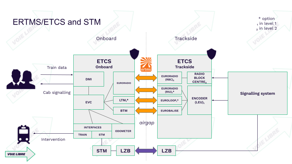
High-level and simplified overview of the ERTMS/ETCS system. It can be observed that some components are optional, while others depend on the application level (1 or 2).
2.3 Application levels
2.3.1 Principles
The different ERTMS/ETCS application levels (short: levels) are a way to express the possible operating relationships between track and train. Level definitions are related to the trackside equipment used, to the way trackside information reaches the onboard units and to which functions are processed in the trackside and in the onboard equipment respectively.
Different levels have been defined to allow each individual railway administration to select the appropriate ERTMS/ETCS application trackside, according to their strategies, to their trackside infrastructure and to the required performance. Furthermore, the different application levels permit the interfacing of individual signalling systems and train control systems to ERTMS/ETCS.
ERTMS/ETCS can be configured to operate in one of the following application levels:
- ERTMS/ETCS Level 0 : train equipped with ERTMS/ETCS operating on a line not equipped with any train control system (ERTMS/ETCS or national system) or on a line equipped with ERTMS/ETCS and/or national system(s) but operation under their supervision is currently not possible.
- ERTMS/ETCS Level NTC : train equipped with ERTMS/ETCS operating on a line equipped with a national system.
- ERTMS/ETCS Application Level 1 with or without infill transmission : train equipped with ERTMS/ETCS operating on a line equipped with Eurobalises and optionally Euroloop or Radio infill.
- ERTMS/ETCS Application Level 2 : train equipped with ERTMS/ETCS operating on a line controlled by a Radio Block Centre and equipped with Eurobalises and Euroradio with train position and train integrity proving performed by the trackside.
- ERTMS/ETCS Application Level 3 : similar to level 2 but with train position and train integrity supervision based on information received from the train.
2.3.2 Level NTC : backward compatibility with Class B systems
Principles
The replacement of Class B systems by ERTMS/ETCS must be synchronized between the tracks and the trains. This represents an immense migration challenge. To facilitate this, the onboard ERTMS/ETCS system has been designed to coexist with Class B systems. This coexistence is enabled by the NTC (National Train Control) level.
At the NTC level, the train is equipped with the ERTMS/ETCS system while the track still has a Class B system. The onboard part of the Class B system can be connected to the ERTMS/ETCS Onboard. This allows for automatic transitions and the sharing of resources such as the cabin display or odometer.
This connection is made via a module called the STM (Specific Transmission Module). The interface between the STM and the ERTMS/ETCS is standardized. The Class B system, through the STM, is responsible for supervising the train at the NTC level.
To operate in France, a new train must be equipped with ERTMS/ETCS as well as a French STM (supporting KVB and/or TVM). Indeed, in 2023, the installation of KVB in a train remains mandatory to operate on the conventional National Railway Network. For high-speed lines, TVM is required.
Thus, Class B systems within the EU have their STM to be connected to ERTMS/ETCS.
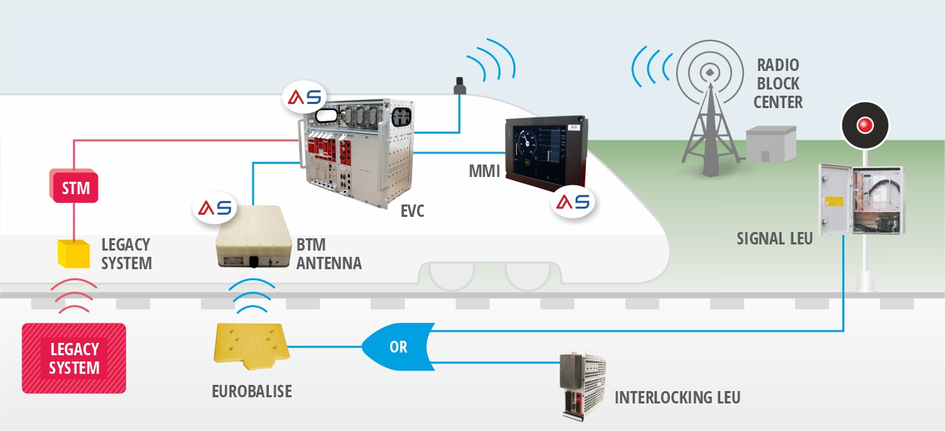
ERTMS/ETCS onboard and trackside equipment, accompanied by the national trackside system and onboard STM. Credit: MERMEC
he national (legacy) system is illustrated in red, with a trackside transmitter and an onboard receiver device in yellow. This device is connected to the STM, which is in turn connected to the EVC. ERTMS/ETCS automatically performs transitions between ETCS levels and NTC level thanks to transition Eurobalises installed on the track.
The driver interacts with ERTMS/ETCS and Class B systems via the single cabin display. This greatly facilitates the driving ergonomics.
The diagram below provides an overview of the ERTMS/ETCS system, with the introduction of the STM module, allowing interfacing with LZB in this example.
The migration challenge and the opportunity of software STM
STM (Specific Transmission Modules) were seen as a migration tool at their inception. Indeed, by enabling a train equipped with ERTMS/ETCS and a set of STMs supporting Class B systems, it was thought that this would trigger a dynamic where:
- Operators start equipping their trains with ERTMS/ETCS, along with STMs and Class B systems to remain compatible with existing infrastructure while waiting for lines to migrate to ERTMS/ETCS.
- Once a significant number of trains equipped with ERTMS/ETCS are in operation, the infrastructure manager initiates the migration of its lines to ERTMS/ETCS.
- Once lines are equipped with ERTMS/ETCS, operators remove STMs and Class B systems from their trains.
- Once trains are fully equipped with ERTMS/ETCS, infrastructure managers complete the migration of their lines to ERTMS/ETCS by removing Class B systems.
This dynamic is unfolding, but at a very slow pace, as migration is a colossal challenge. It involves dual equipment both on the trackside and on board, spanning decades.
Given that the European rail area is still highly fragmented by Class B systems on the trackside, adaptation occurs onboard, integrating a plethora of Class B systems and associated STMs to cross borders. These are multi-system trains, and they are very costly, considering the complexity of integrating STMs, Class B systems, and associated antennas.
A key innovation is to no longer have a hardware STM module but a software one. The STMs become software hosted directly in the EVC (European Vital Computer), along with the associated Class B system. The onboard computer then becomes Multistandard, a fundamental tool for migration.
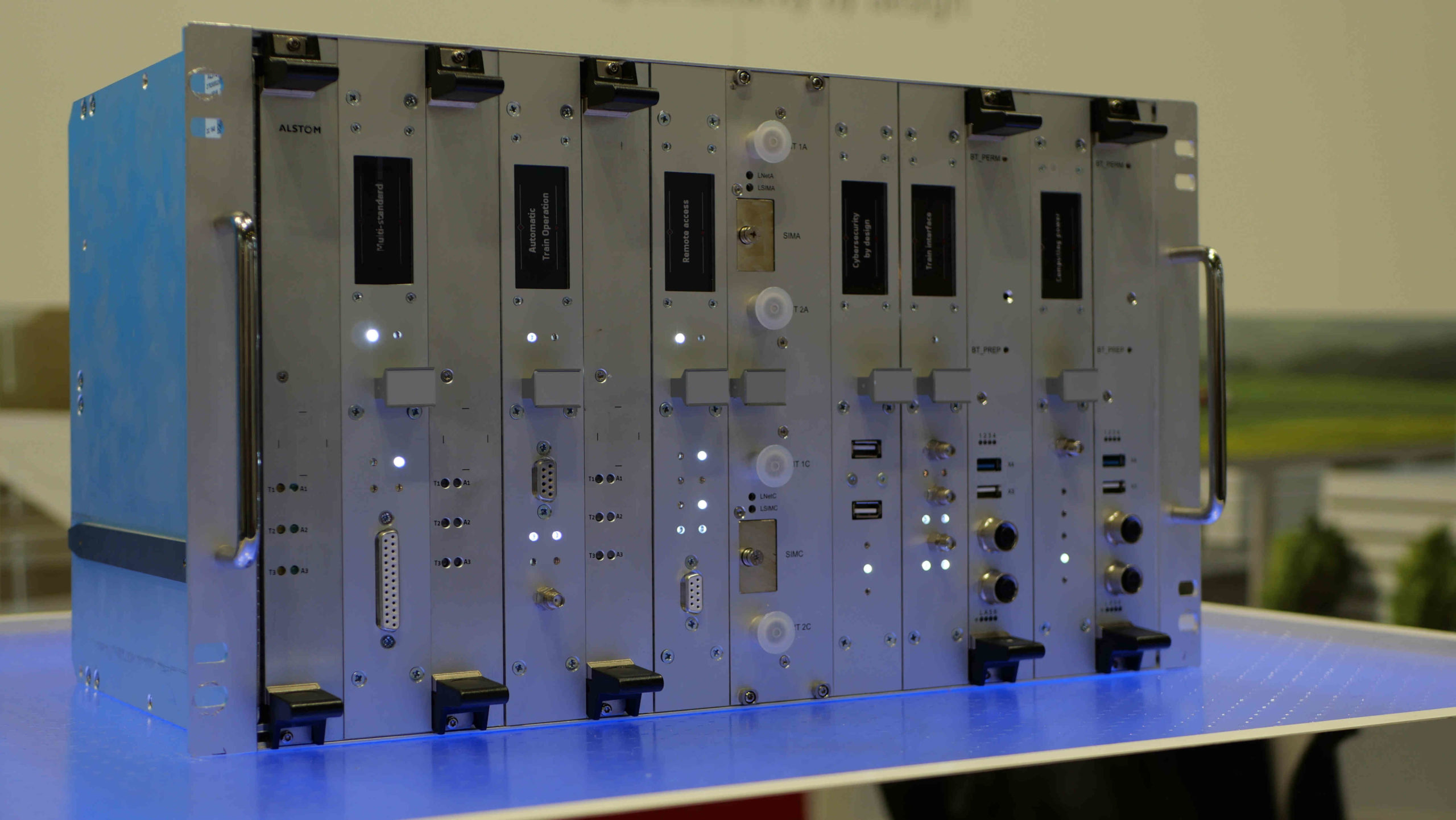
Onboard computing unit ALSTOM ATLAS EVC3, revealed during Innotrans 2022. Credit: Bastian SIMONI
This onboard unit can host ERTMS/ETCS, Automatic Train Operation (ERTMS/ATO) and STM+class B systems as software (Multistandard platform).
2.3.3 Level 1 : the upgrade based on existing systems
ERTMS/ETCS Level 1 is a spot transmission-based train control system to be used as overlay on an underlying signalling system. Movement Authorities are generated trackside and transmitted to the onboard via Eurobalises, fed by Lineside Electronic Units (LEU).
Level 1 provides a continuous speed supervision system, which also protects against overrun of the authority.
Train detection and train integrity supervision are performed by the trackside equipment of the underlying signalling system (interlocking, track circuits, axle counters, etc) and are outside the scope of ERTMS/ETCS.
A fundamental step of an ERTMS/ETCS Level 1 project, is the application engineering. Indeed, this step consists in studying the line on which Level 1 will be deployed, and to create all necessary ERTMS/ETCS compliant data.
These data are put into the coders (LEU) installed on the line. The coders can be connected to the interlockings or the lineside signals. The LEUs are programmed with the application engineering data, with all ERTMS/ETCS data associated to the interlocking or the signal they are connected to. The LEU transmits to the Eurobalise the proper ERTMS/ETCS data, related to the state of the interlocking or the signal, as defined during the application engineering process.
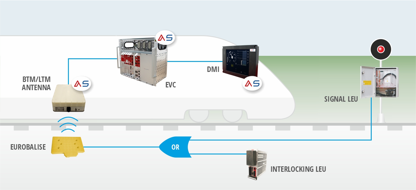
This scheme represents the flow of signalling information, starting from the signal or interlocking, retrieved by a LEU that sends the corresponding ERTMS/ETCS data to the Eurobalise, fetched by the onboard Balise Transmission Module (BTM) and EVC, and then displayed to the driver on the Driver Machine Interface. Credit : MERMEC
Level 1 when approaching a red signal.

Representation of Level 1 : red signal approach, only equipped with Eurobalises. Credit : ertms.net
The signal is closed (red), the state is retrieved by the LEU, that associates this state with ERTMS/ETCS compliant data defined during the application engineering phase. If the signal remains red, the driver must not pass the Eurobalise. By doing so, the onboard would automatically apply the emergency brake. The driver must wait until the signal is open to cross the Eurobalise. The signal LEU would have modified the ERTMS/ETCS data in the balise, and the onboard would receive its new Movement Authority.
Level 1 being a spot transmission system, existing lineside signalling must be kept. It is not a 100% CAB-signalling system. Semi-continuous infill devices can enable CAB-signalling and then the lineside signals can be suppressed. These devices are:
- Euroloops, inductive loops placed before the Eurobalise,
- Radio Infill Units (RIU), a local radio transmission device, placed at the foot of the signal.
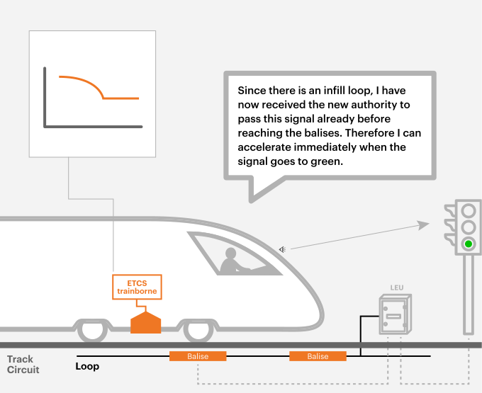
Representation of Level 1 : red signal approach, equipped with Euroloop. Credit ertms.net
If the signal is equipped with infill devices, like Euroloop or RIU, then the onboard receives immediately the new Movement Authority when the signal is open.
On the scheme, the black line represents an inductive loop Euroloop, that transmits continuously the ERTMS/ETCS data provided by the LEU and associated to the state of the signal. Although the train antenna has not yet crossed the balise, it is above the loop and receives the refreshed Movement Authority immediately when the signal state changes.
The future of Level 1
In 2023, Level 1 is considered outdated by the railway sector for several reasons:
- Level 1 is a tool for installing ERTMS/ETCS and train protection functionality overlaying the lineside signals. It adds operating costs to the infrastructure. However, the trend is towards simplification and cost reduction.
- Due to its semi-continuous communication, Level 1 does not allow a line’s capacity to reach its full potential. Semi-continuous communication devices like Euroloops and Radio Infill Units can no longer be installed on the trackside, according to the Technical Specification for Interoperability – Control-Command and Signaling.
The target system, as defined by Europe’s Rail System Pillar, is exclusively based on Level 2.
2.3.4 Level 2 : radio signalling
ERTMS/ETCS Level 2 is a radio-based train control system which is used as an overlay on an underlying signalling system. Movement Authorities are generated trackside and are transmitted to the train via Euroradio. For that, a Radio Block Centre is connected to the existing or upgraded interlocking.
ERTMS/ETCS Level 2 provides a continuous speed supervision system, which also protects against overrun of the authority.
Train detection and train integrity supervision are performed by the trackside equipment of the underlying signalling system (interlocking, track circuits, axle counters, etc) and are outside the scope of ERTMS/ETCS.
Level 2 is based on Euroradio for track to train communication and on Eurobalises as spot transmission devices mainly for location referencing.
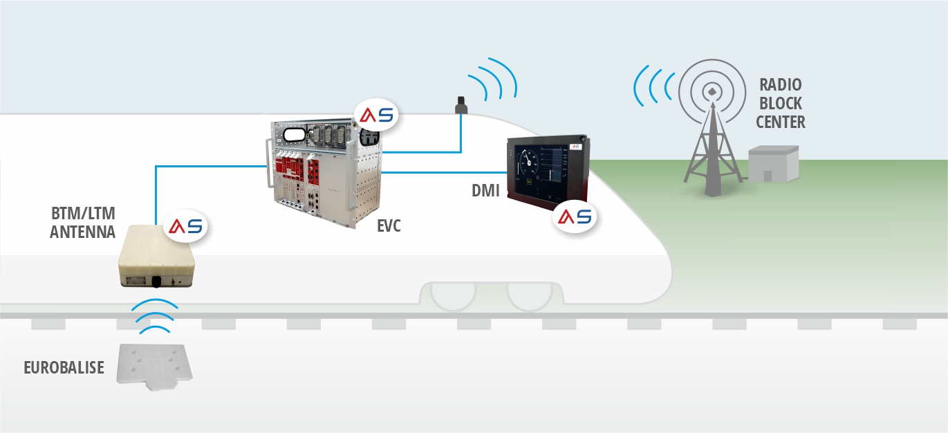
ERTMS/ETCS Level 2, credit MERMEC.
2.3.5 : Level 2 without Track Train Detection
Formerly known as Level 3 (SUBSET-026 version 3.6.0), this particular implementation of Level 2 assumes that the movement authority is generated by the Radio Block Centre (RBC), based on the train’s location and integrity. The movement authority is transmitted to the train via a radio link: Euroradio.
In this level, the train reports its location on the track and its integrity control to the RBC. A device checks that no part of the train has become detached, which is the role of the TIMS (Train Integrity Monitoring System).
Thus, there is no longer a need for track circuits or axle counters to verify the occupancy status of sections. Consequently, there is no longer a physical constraint on the track, which requires division into sections. This allows for a transition from a train spacing management based on fixed sections to one based on the moving block.
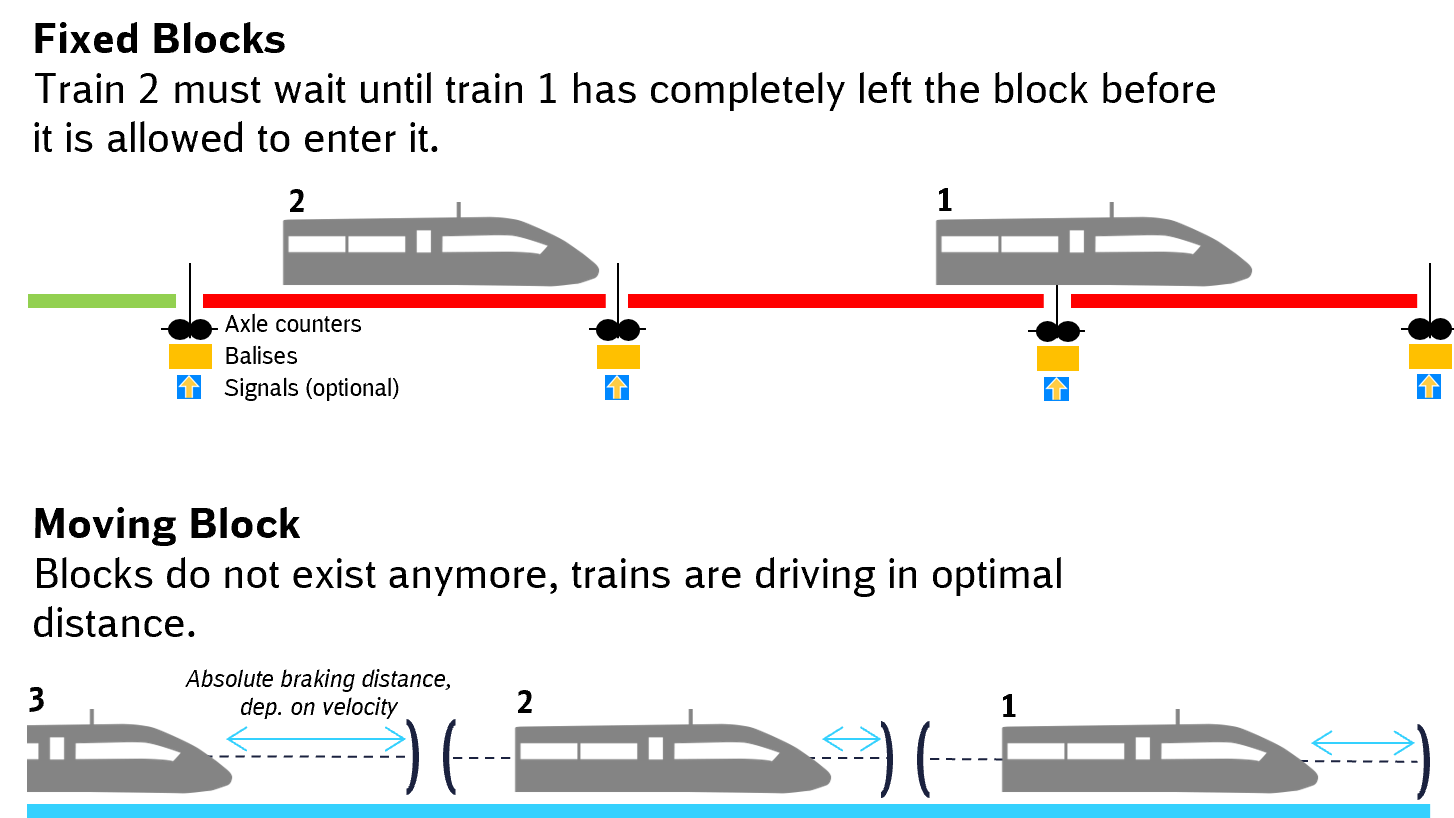
The figure above (credit Digitale Schiene Deutschland) illustrates the point.
In the first part, we have a line equipped with information points, delineating the sections, where we find axle counters, a group of balises, and an optional signal. As long as train 1 does not completely vacate the section, train 2 is stopped because it cannot enter the occupied section.
In the second part, there is no longer a train detection system on the track, and therefore no physical delineation of sections. The spacing between trains is directly managed by the RBC, which takes into account the position, speed, and characteristics of each train. The result is an increased line capacity, with the spacing between trains reduced to the minimum required.
Interlocking functions can be directly integrated into the RBC, known as the Advanced Protection System (APS). Lineside signaling is no longer necessary. Some Eurobalises remain necessary to ensure train localization.
Hybrid Level 3
Hybrid Level 3 is a specific concept for the implementation of Level 2 without Track Train Detection, defined by the ERTMS Users Group. The main characteristic of the concept is that it uses fixed virtual blocks for the separation of trains which are fitted with a train integrity monitoring system (TIMS), while a limited installation of trackside train detection is used for the separation of trains without TIMS, as well as for the handling of degraded situations.
ERTMS/ETCS Level 2 without Track Train Detection relies on preconditions, that are difficult to match in 2023:
- In Level 2 without Track Train Detection, the separation of trains is managed by ERTMS/ETCS, thanks to the position and integrity reports of the trains. Each train must be equipped with a TIMS, and the use of TIMS on variable composition trains (especially freight) is complex,
- The total absence of train detection devices trackside supposes that ERTMS/ETCS Level 2 without Track Train Detection knows at any moment the position and integrity of all trains within the area under its responsibility. In practice, this is not always possible:
- If the train is moved via operational procedures, not under the supervision of ERTMS/ETCS,
- If the radio communication fails.
Hybrid Level 3 is an interesting answer to the challenges of Level 2 without Track Train Detection. Indeed, keeping a trackside train detection system enables:
- The compatibility with freight trains, for which the use of TIMS is complex today. It will be facilitated in the future with the Digital Automatic Coupling (DAC),
- The management of trains disconnected from the trackside hybrid level 3, as they will still be detected by the train detection system. This is particularly interesting for movements via operational procedures, or in case of rebooting of the trackside in case of a crash.
In its concept, Hybrid Level 3 does not use virtual moving block, but virtual fixed block. This is not a fundamental need of the concept. It is just for pragmatic reasons. In comparison to moving blocks, fixed virtual blocks have in several implementations less impact on the existing trackside systems such as the RBC, interlocking and traffic control centre as well as on the operational procedures. By reducing the length of the virtual blocks, the performance can be similar to moving blocks, which means that the performance benefit is not compromised.
3. ERTMS/ETCS architecture
3.1 Architecture of ERTMS/ETCS
When ERTMS/ETCS was specified, interoperability was a fundamental aspect. The objective was to enable smooth border crossing, but also the possibility to use onboard ERTMS/ETCS from supplier A in combination with a trackside from supplier B.
The specification of ERTMS/ETCS defines the system architecture, with plug’n’play interfaces FFFIS (Form-Fit Function Interface Specification).
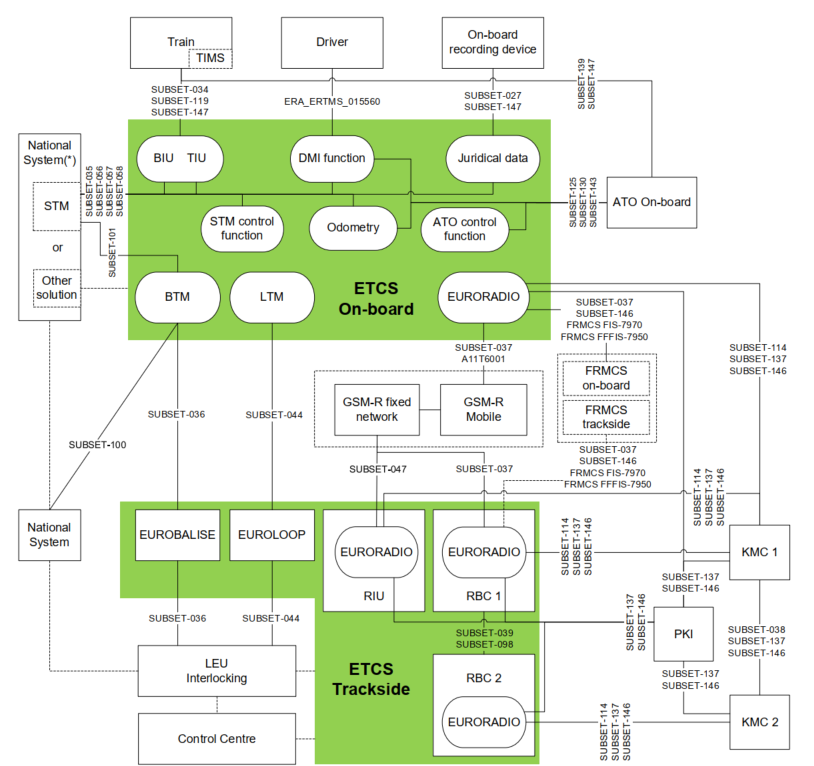
ERTMS/ETCS architecture according to SUBSET-026 §2 version 4.0.0
The onboard ERTMS/ETCS contains :
- BIU/TIU : the module that interfaces with the train, notably to apply the emergency braking,
- DMI : Driver Machine Interface,
- Juridical data : the interface function with the onboard recording device,
- BTM : Balise Transmission Module, the device that retrieves the information from the Eurobalises,
- LTM : Loop Transmission Module, the device that retrieves the information from the Euroloops,
- Euroradio : the GSM-R modem.
The trackside ERTMS/ETCS contains :
- RIU : Radio Infill Unit, providing signalling information in advance as regard to the next main signal in the train running direction,
- RBC : Radio Block Centre, a computer-based system that elaborates messages to be sent to the train on basis of information received from external signalling systems (e.g. interlocking) and on basis of information exchanged with the onboard subsystems,
- Balises : a transmission device that can send telegrams to the onboard subsystem,
- Euroloops : inductive loops providing signalling information in advance as regard to the next main signal in the train running direction.
Trackside elements around the ERTMS/ETCS scope (in green) are :
- LEU/interlocking : the lineside electronic units are electronic devices, that generate telegrams to be sent by balises, on basis of information received from external trackside systems,
- KMC : the role of the KMC is to manage the cryptographic keys, which are used to secure the Euroradio communications between ERTMS/ETCS entities,
- PKI : the role of the PKI is to manage and distribute digital certificates, so to allow a secure online distribution of cryptographic keys between KMCs and from a KMC to the ERTMS/ETCS entities,
- Control Centre
- National System : existing class B systems
3.2 The interface with the driver
ERTMS/ETCS is an ATP, enabling cab signaling. As ERTMS/ETCS is intended to be used throughout the Union, the interface between the system and the driver is also standardized. Indeed, having a different interface per country is unthinkable! This ultimately allows drivers from all over the Union to be exclusively trained in the use of ERTMS/ETCS.
Thus, everything displayed on the DMI is subject to a specification maintained by the ERA: ERA_ERTMS_015560.

Credit : ALSTOM
4. ERTMS/ETCS blind spots
4.1 The long-lasting rollout of ERTMS/ETCS
Since its conception in the 1990’s and its first deployments, the rollout rhythm of ERTMS/ETCS is slow. Although it is meant to replace existing class B systems, and facilitate interoperability, a massive rollout of ERTMS/ETCS is still awaited.
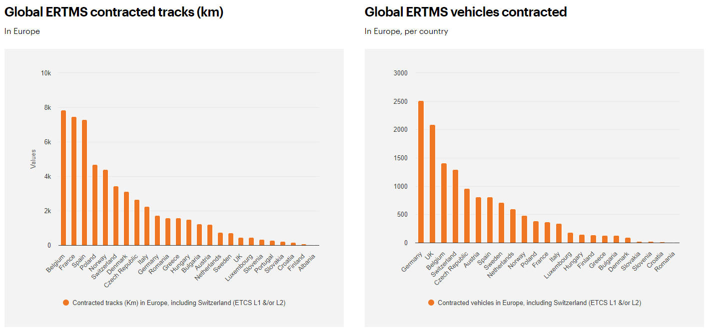
Deployment data (stand 12/2023), credit ertms.net
The German association Allianz Pro Schiene shared in November 2022, helped with SCI Verkehr data, its comprehension of the ERTMS/ETCS rollout plans in some European countries. We can discover that 20% of French and German networks will be covered by ERTMS/ETCS in 2030. Projection of 90% of the network is expected in 2040.
In real terms, this means that from now on to 2040 :
- Class B systems will remain inescapable: software STMs and Multistandard platforms will be a must,
- The ATO over ETCS solution, as defined in 2022, is not massively usable until 2040. Indeed, automatic traction and braking, in presence of a driver, needs ERTMS/ETCS installed both onboard and trackside!

4.2 The difficult integration
4.2.1 The problem
ERTMS/ETCS is a system, with many interfaces standardized through SUBSETs. At first glance, one might think that deploying ERTMS/ETCS equipment, on the trackside or on trains, is easy. The reality is quite different.
ERTMS/ETCS is integrated into an existing railway system that is very heterogeneous. This means that the existing equipment to which ERTMS/ETCS components connect has never been designed for this purpose! Existing equipment is highly diverse, with specific principles. As a result, for each ERTMS/ETCS deployment project, engineering studies and specific developments must be carried out to account for the particularities of existing equipment. Let’s delve into this in more detail.
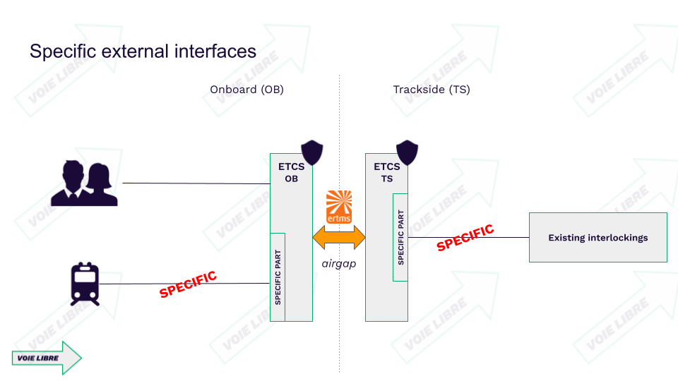
4.2.2 Onboard integration
Existing trains have never been predisposed to accommodate ERTMS/ETCS. It’s only been in recent years that every new train produced must inherently integrate ERTMS/ETCS (and STM and class B systems if applicable).
This means concretely that installing ERTMS/ETCS on an existing train requires:
- Mechanical engineering studies to determine where and how to install the equipment on the train.
- System studies to determine how to connect the ERTMS/ETCS computer to the train’s computer and electro-mechanical interfaces.
For each series of locomotives or trains, these studies need to be repeated!
Installing ERTMS/ETCS on board a train is a separate project. And projects, in turn, require a lot of resources, both human and financial. This is currently a barrier to widespread deployment.
One way to reduce installation complexity, especially on the train interface, is the concept of the Functional Vehicle Adapter (FVA) developed by OCORA. This train adapter would allow the use of SUBSETs of the train interface (SUBSET 034, 119, 147) between the ERTMS/ETCS computer and the adapter. The FVA would then handle the mapping to the specific interface of the train. Thus, it’s the FVA that would carry the train’s specificities, not the EVC.
Another approach is to harmonize the principles of computer interfaces. This is the ambition of SUBSET-147, also called One Common Bus, which aims to converge towards a single computer communication bus between onboard equipment.
4.2.3 Trackside integration
Deploying ERTMS/ETCS on the trackside poses exactly the same problems as on board trains.
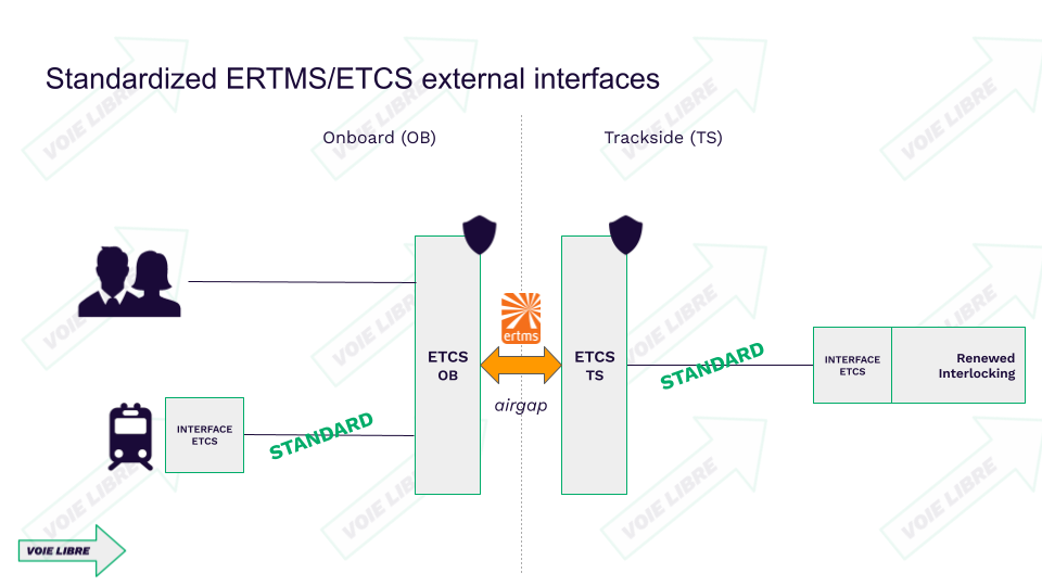
ERTMS/ETCS on the trackside simply adapts existing signaling information into the ETCS format. And this information comes from existing systems: interlockings. Each country in Europe has had its own approach to interlocking systems, and the fleet is far from uniform: relay interlockings, electronic interlockings, digital interlockings…
Thus, for each deployment of an RBC, an interface with the existing interlocking must be developed. Like with onboard deployment, this involves conducting projects that require significant resources.
To address this issue, a comprehensive modernization approach must be considered, including:
- Defining a standardized interface between interlocking and RBC.
- Replacing existing interlockings with digital interlockings, equipped with the standardized interface for RBC.
- Installing RBCs adjacent to the new interlockings, using the standardized interface, during the deployment of ERTMS/ETCS on the modernized line.
The definition of a standardized interface at the European level between RBC and interlocking is currently underway within Europe’s Rail System Pillar.
Another solution is to move directly to level 2 without trackside train detection. The line would be deeply modernized and simplified, and the installed RBC could directly integrate interlocking functions (Advanced Protection System principle).
4.3 The goal : defining migration paths
The objective towards which the entire Union aims is straightforward: the target system by 2050.
For ERTMS/ETCS, the goal is to have migrated to level 2 wherever interoperability is required. There will be no more class B systems, no more STM, or equipment necessary for level 1 (LTM, RIU), on the interoperable network.
Once the objective is clear, it is necessary to outline the trajectory to achieve it. Trajectories are specific to each country, as the starting situations are all unique.
The Migration group within Europe’s Rail System Pillar is currently specifying the broad outlines of these trajectories, in collaboration with operators and industry stakeholders. Once these broad outlines are defined, each country will then need to get to work and initiate the migration process.
Synthesis
In order to improve the safety of railway operations, many countries in Europe have adopted Automatic Train Protection (ATP) systems. Following the principle of “Ten engineers, ten solutions,” ATP systems in Europe all have their own specificities. This has made cross-border railway operations even more challenging, as trains must be equipped with all the ATP systems required by the different countries they pass through.
To address this situation and contribute to interoperability, a European Automatic Train Protection system was designed: ERTMS/ETCS.
Consisting of trackside equipment and onboard trains, ERTMS/ETCS has the main functions of providing signaling information in the cabin and supervising driving.
Different levels of application are proposed: 0, 1, 2, and NTC. They allow for a progressive migration between train equipment and track equipment. The different operating modes of the onboard equipment indicate the responsibilities between the ERTMS/ETCS system and the driver.
Twenty years after being specified by operators and manufacturers, the ERTMS/ETCS system is still deployed to a limited extent, both on the ground and onboard trains. One reason is the lack of strong political will for a significant deployment of ERTMS/ETCS. Another reason lies in the difficulties of integrating ERTMS/ETCS into the existing railway system.
Solutions to these integration challenges are starting to emerge. The goal is to scale up and move towards a massive deployment of the ERTMS/ETCS system in the Union. To achieve this, it will be necessary to move towards a logic of harmonized, mass-deployable products. This is the mandate of the Europe’s Rail initiative, which continues the work of harmonization, both operationally and technically, to address all the still-specific parts of ERTMS/ETCS.
On the technological front, ERTMS/ETCS continues to evolve. Specifications for level 2 without trackside train detection, hybrid level 3, and absolute positioning are underway in R2DATO.
The introduction of compatibility with Automatic Train Operation (ATO) and with the FRMCS ground-to-train communication were the major innovations of ERTMS/ETCS in 2023.
ERTMS/ETCS documentation
Technical Specification for Interoperability – Control-Command and Signalling (2023)
- ERTMS/ETCS specification : SUBSET-026
- More SUBSETs available in the TSI CCS Appendix A : link
Documentation released by European R&I programs
Advanced Safe Train Positioning
- X2RAIL-5 project : « Fail-safe Train Positioning Specification » Deliverable D5.4 Gap Analysis
- X2RAIL-5 project : « Fail-safe Train Positioning Specification » Deliverable D5.5 Roadmap and Migration Strategy
- X2RAIL-5 project : « Fail-safe Train Positioning Specification » Deliverable D5.1 VB Train Positioning Specification
- X2RAIL-5 project : « Fail-safe Train Positioning Specification » Deliverable D5.2 Stand Alone Train Positioning Specification
- X2RAIL-5 project : « Fail-safe Train Positioning Specification » Deliverable D5.3 Contribution to the standardisation
- X2RAIL-5 project : « Stand-alone fail-safe Train Positioning » Deliverable D7.3 Prototypes Developments Report
- X2RAIL-5 project : « Stand-alone fail-safe Train Positioning » Deliverable D7.4 Broader Statistical Evaluation
- X2RAIL-5 project : « Stand-alone fail-safe Train Positioning » Deliverable D7.5 Stand Alone Test Report
- X2RAIL-5 project : « Virtual Balise Fail-Safe Train Positioning » Deliverable D6.2 Updated Test Scenarios
- X2RAIL-5 project : “Stand-Alone Fail-Safe Train Positioning” Deliverable D7.1 Laboratory Description
- X2RAIL-5 project : “Stand-Alone Fail-Safe Train Positioning” Deliverable D7.2 Demonstrator Definition & Test Scenarios
- X2RAIL-5 project : “Virtual Balise Fail-Safe Train Positioning » Deliverable D6.1 Prototypes test bench
- X2RAIL-5 project : “Virtual Balise Fail-Safe Train Positioning » Deliverable D6.3 Demonstrators Analysis and Test Report
- X2RAIL-2 project : Architecture for Stand Alone Fail-Safe Train Positioning documentation
- X2RAIL-2 project : System requirements specification of the fail-safe train positioning functional block documentation
- X2RAIL-2 project : Stand alone system requirements specification for fail-safe train positioning documentation
Moving Block
- X2RAIL-5 project : « Moving Block » Deliverable D4.1 Moving Block Specification – Part 1 Introduction
- X2RAIL-5 project : « Moving Block » Deliverable D4.1 Moving Block Specification – Part 2 System Definition
- X2RAIL-5 project : « Moving Block » Deliverable D4.1 Moving Block Specification – Part 3 System Specification
- X2RAIL-5 project : « Moving Block » Deliverable D4.1 Moving Block Specification – Part 4 Operational Rules
- X2RAIL-5 project : « Moving Block » Deliverable D4.1 Moving Block Specification – Part 5 Engineering Rules
- X2RAIL-5 project : « Moving Block » Deliverable D4.1 Moving Block Specification – Part 6 Safety Analysis
- X2RAIL-5 project : « Moving Block » Deliverable D4.2 Moving Block Enhancements
- X2RAIL-5 project : « Moving Block » Deliverable D4.3 Report for Moving Block Technical Demonstrators
- X2RAIL-3 project : Report on testing of moving block signalling systems
- X2RAIL-3 project : Moving Block Specifications
- X2RAIL-3 project : Future Moving Block Architectures
- X2RAIL-3 project : Report on Technical Demonstrators
- X2RAIL-1 project : Moving Block System Requirements documentation
- X2RAIL-1 project : Moving Block Operational Engineering Rules documentation
- X2RAIL-1 project : Moving Block Preliminary Safety Analysis documentation
- X2RAIL-1 project : Moving Block Application Report documentation
Train Integrity and Monitoring System
- X2RAIL-2 project : Train Integrity Concept and Functional Requirement Specification
- X2RAIL-2 project : Functional architecture & Interfaces specifications & Candidate technologies selection documentation
- X2RAIL-2 project : Test scenarios, test cases and test procedures definition documentation
Next article : ERTMS/ATO, the european train autopilot
Cover picture credit : ALSTOM
